Issue No. 251〔Technical Papers〕
Numerical Simulation of Welding Deformation produced in Compressor Impeller
Author
Shinji KOBAYASHI*
Esao YAMADA**
Tetsu GO**
Shigetaka OKANO***
Masahito MOCHIZUKI***
Kenyu KIMURA****
Akiyoshi ANDO****
- *
- Production Process Innovation Division (Formerly Graduate School, Osaka University)
- **
- Production Process Innovation Division
- ***
Graduate School, Osaka University
- ****
Elliott Ebara Turbomachinery Corporation
Among many problems with welding is welding distortion. Since welding distortion significantly affects the performance and reliability of products, it has become increasingly required in recent years to appropriately foresee, control, and reduce distortion. One of the approaches to this issue is numerical analysis. As significant improvements have been made to welding dis- tortion analysis technology, its application has been increasing every year. So far, however, numerical analysis has only been applied to a limited number of large scale and/or complicated structures. Under such circumstances, with a compressor impel-ler having complicated structure as a target, distortion analysis and experiment was performed. The analysis and experiment results have revealed that it is possible to evaluate welding distortion occurring to an impeller with high accuracy by using numerical analysis with the help of the construction of a heat source model and taking into account phase transformation.
Keywords: Compressor, Impeller, Welding distortion, Numerical simulation, Distortion measurement, Phase transformation, Martensitic stainless steel, Displacement of discharge width, Displacement of cover height
1. Introduction
In fabricating machines and structures, welding plays an important part as a basic manufacturing technology. However, welding can be accompanied by defects such as poor welds and cracks, unevenness in strength and toughness ascribable to a heat-affected zone, mismatch in the shape of, for example, a bead toe, and residual stress and distortion, which may result in the decreased strength of the structure and other problems. These phenomena must be appropriately predicted evaluated, and controlled to build sound welded joints/structures.
In recent years significant improvement has been made in numerical simulation technology for welding distortion and residual stress1), 2), enabling more accurate prediction and evaluation of welding distortion. This improvement has largely resulted from the introduction of modeling technologies that take into consideration the material behavior associated with the thermal cycles of phase transformation3) and recovery4)/recrystallization as well as heat source characteristics5) based on welding arc physics. So far, however, numerical simulation has only been applied to limited numbers of actual machines and similar complicated/large structures.
In this study, we performed numerical simulation of welding distortion occurring in a compressor impeller with a complicated shape and conducted experimental measurements to compare and verify the simulation and measurement results as well as examine the occurrence characteristics of welding distortion.
2. Numerical simulation of welding distortion occurring in a compressor impeller and measurement experiment
2.1 Compressor impeller and the welding conditions for it

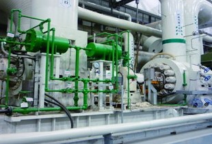
Fig. 1 General view of the compressor impeller

Fig. 2 Welding sequence
2.2 Numerical simulation
Figure 3 shows a finite element model of the compressor impeller. As the boundary condition in heat transfer analysis, heat transmission and the thermal radiation that obeyed the Stefan-Boltzmann law was considered, and as the boundary condition in thermo-elastic-plastic analysis, the model is restricted only the rigid-body movement and rotation. Figure 4 shows examples of material properties used for the numerical analysis. In order to take into consideration the phase transformation behavior associated with the thermal cycle, yield stress and the temperature dependence of the linear expansion coefficient (thermal strain curve) as shown in the figure were used in numerical analysis. A heat-source model was modeled by reference to the temperature history and angular distortion at the welds of T-shaped fillet welded joints observed with the same welding heat input as for the compressor impeller. In this analysis, heat source length was 6 mm, and thermal efficiency was 0.6.

Fig. 3 Finite element model of the compressor impeller

Fig. 4 Material properties used in numerical analysis in consideration of phase transformation
2.3 Procedure for evaluating welding distortion

Fig. 5 Measurement targets and their positions
3. Results of the numerical simulation of welding distortion occurring in the compressor impeller and experimental measurements
3.1 Comparison between the results of the numerical simulation on the occurrence characteristics of welding distortion in the compressor impeller and experimental measurements

Fig. 6 Simulated and measured displacement H

Fig. 7 Simulated and measured displacement C
3.2 Consideration of the occurrence characteristics of welding distortion in a compressor impeller
4. Conclusion
- (1)
- The welding distortions in the compressor impeller obtained through the numerical simulation performed in this study substantially agree with the experimental measurement results quantitatively or otherwise, revealing that the simulation is accurate.
- (2)
- The review result of the welding distortions occurring in the compressor impeller has revealed that while radial-direction distortions are not so large, the following distortions are relatively large: a distortion observed as a fall of the cover rim in the hub (displacement of cover height) and a distortion observed as a decreased discharge width between the hub and the cover of each blade (displacement of discharge width).
- (3)
- The displacement of discharge width is large when two blades to the sides of the discharge width are welded, which is deemed to be caused by angular distortion.
- (4)
- The displacement of the cover height is deemed to be caused by shrinkage along the welding lines; in some cases, a large displacement is observed even when a blade away from the measurement position is welded. This suggests that this distortion can be also caused by the balance of the entire structure with a complicated shape.
5. Acknowledgments
References
Recommended articles

Inquiry about Ebara Engineering Review