Issue No. 252〔New Products & New Techniques〕
Model EVMS Vertical Multistage Pumps
for the Global Market
Author
Hiroyuki KAWASAKI*
So KUROIWA*
- *
Fluid Machinery & Systems Company
1. Introduction
Our new model EVMS jointly developed with EBARA PUMPS EUROPE S.p.A., an Italy based firm, is a full model change of the previous model EVM stainless steel vertical multi-stage pumps. This new model uses a redesigned impeller, with the objectives of reducing much axial thrust force resulting from the multi-stage impeller, and of achieving improved pump performance. In addition, the new model offers more choices for pipe connections to meet the needs of assembled product manufacturers in particular.
This paper will outline the model EVMS vertical multi-stage pumps for global markets, and descri their features.
2. Product outline

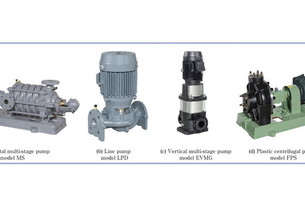
Fig. 1 Appearances of model EVMS vertical multi-stage pumps for global markets
| Item | EVMSG | EVMS | EVMSL | |
| Application | Boiler feeding and coolant supply | Supply of drinking and hot water | Use in water purification systems | |
| Fluid | Liquid type | Industrial water | Clean water | Pure water |
| Temperature | - 30 to 140 °C [- 15 to 120 °C] | |||
| Bore (mm) | 25, 32, 40, and 50 | |||
| Total suction head | −6 m(20 ℃) : 25S/25/32/40 | |||
| −5 m(20 ℃) : 50/50 L | ||||
| Maximum operating pressure | 1.4/2.5 MPa | |||
| Standard allowable boost pressure | Maximum operating pressure - shutoff pressure | |||
| Structure | Impeller | Closed type with a single liner | ||
| Intermediate casing | Ring section type with returning blades | |||
| Casing ring | Floating type | |||
| Lower casing | Inline-type | |||
| Mechanical seal | Cartridge mechanical seal | |||
| Ball bearing | Sealed ball bearing (inside the motor) | |||
| Sliding bearing | Submerged sleeve bearing | |||
| Pipe connection | Oval, DIN and ANSI | Oval, DIN, ANSI, JIS, and grooved pipe couplings. | ||
| Material | Impeller | EN 1.4301 (AISI 304) | EN 1.4401 (AISI 316) | |
| Intermediate casing | EN 1.4301 (AISI 304) | EN 1.4401 (AISI 316) | ||
| Casing ring | EN 1.4301 (AISI 304)+PPS | |||
| Lower casing | FC250 | EN 1.4301 (AISI 304) | EN 1.4401 (AISI 316) | |
| Sliding bearing | Tungsten carbide | |||
| Main shaft | EN 1.4301 (AISI 304)/EN 1.4460 (AISI 329A) | EN 1.4401 (AISI 316)/EN 1.4460 (AISI 329A) | ||
| Shaft sleeve | EN 1.4301 (AISI 304) | EN 1.4401 (AISI 316) | ||
| Mechanical seal | SiC, carbon, and FPM | |||
| O-ring | EPDM (standard) or FPM (optional) [FPM] | |||
| Output range | 0.37 to 18.5 kW | |||
| Numbers of phases and poles | Three phases and two poles | |||
| Voltage | 200 V・50 Hz | |||
| 200/220 V・60 Hz | ||||
| Type and protection scheme | Totally-enclosed fan-cooled type with IP55 protection | |||
| Efficiency level ** | IE3, premium efficiency | |||
| Installation location | Indoor and outdoor | |||
** Output less than 0.75 kW is regarded as premium efficiency class (our definition)

Fig. 2 Performance range (50 Hz)

Fig. 3 Performance range (60 Hz)

Fig. 4 Structure of a typical EVMS-series model
2.1 Product specifications
2.2 Performance
The previous EVM series consisted of four models (EVM3, EVM5, EVM10, and EVM18). The new EVMS series has included two more models—the EVMS1 with a water volume lower than that of the EVM3, and the EVMS20 with a water volume higher than that of the EVM18—totaling six models (EVMS1, EVMS3, EVMS5, EVMS10, EVMS15, and EVMS20). The number (e.g., 3) included in each model name represents the nominal discharge rate (m3/h).
Each model supports a variety of pump heads up to 200 m and motors of up to 18.5 kW.
Bore: 25, 32, 40, and 50 mm
Flow rate range: 0.012 to 0.48 m3/min. (50 Hz)
0.013 to 0.56 m3/min. (60 Hz)
2.3 Structure
The lower casing is made of pressed stainless steel or cast iron. The bracket unit consists of a motor bracket for supporting internal pressure, operation torque, and the weight of the motor, and a casing cover made of pressed stainless steel sheet for preventing rust at the part that contacts liquid. The casing cover is equipped with an air vent plug, in addition to the priming water plug, which was also installed in the previous models, to ensure complete air removal.
All of the impellers are closed type and made of pressed stainless steel. Each of the intermediate casings is equipped with returning blades for guiding the fluid from the impeller to the next stage.
The motor torque is transferred through the coupling to the main shaft. The main shaft is splined, transferring the torque to each impeller. Inside the pump, a submerged bearing made of cemented carbide (tungsten carbide) is arranged as required to control axial runout. The axial thrust force applied to the main shaft during pump operation is absorbed by a sealed ball bearing installed inside the motor. The approach to reducing axial thrust force will be described in detail in the“ Features” section that follows.
3. Features
3.1 Development of a new impeller (reduced axial thrust force and improved performance)
A radial impeller rotating in liquid produces a centrifugal effect, which develops a discharge pressure. The difference between the discharge pressure and suction pressure causes axial thrust force to act on the impeller. An impeller, if multi-stage, produces axial thrust force that increases in proportion to the number of stages. To absorb this thrust force, the previous model EVM uses a combination of a pump-side bearing for absorbing high axial thrust force and a housing for supporting this bearing, or uses, as the bearing built into the motor, a purpose-built bearing capable of enduring high axial thrust force. Figure 5 shows the direction in which the axial thrust force acts and the location of the pump-side bearing for countering the thrust force.

Fig. 5 Countermeasures against axial thrust used
in the previous model EVM
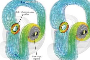
For the purpose of explaining how axial thrust force acts on the impeller, Figure 6 shows the previous impeller used in the model EVM, seen from the main shroud, and Figure 7, how axial thrust force acts on the impeller. Figure 8 shows the distribution of pressure that acts on the main shroud.
As shown in Fig. 8, the pressure is highest at the rim of the shroud.

Fig. 6 Impeller used in the previous model EVM
(seen from the main shroud)

Fig. 7 Axial thrust force acting on the impeller
in the previous model EVM

Fig. 8 Pressure distribution in the main shroud of the
impeller used in the previous model EVM
The new impeller we have developed this time reduces the axial thrust force that acts on the impeller during operation by using a uniquely shaped impeller main shroud with the most pressurized part partially removed. The blue line in the figure represents the unique shape of the main shroud of the new impeller. Figure 9 shows the new impeller seen from the main shroud, and Figure 10, how axial thrust force acts on the new impeller.

Fig. 9 New impeller (seen from the main shroud)

Fig. 10 Axial thrust force acting on the new impeller
Actual measurement results have demonstrated that the axial thrust force is significantly lower than that of the previous model EVM; the measurement results are shown in Figure 11. The shaded bars in the figure represent the target values of axial thrust forces. If the actual thrust force does not exceed these targets, no pump-side bearing is required and it is possible to use a standard motor without a purpose built bearing that endures high axial thrust force, offering a wider choice of motors.
Figures 12 and 13 show some of the performance improvements achieved by the new impeller. They indicate that compared with the previous model EVM, the new impeller exhibits significantly improved QH performance and efficiency.

Fig. 11 Comparison of axial thrust force between the
previous model EVM and new model EVMS

Fig. 12 Performance comparison between the previous
model EVM and new model EVMS (50 Hz)

Fig. 13 Performance comparison between the previous
model EVM and new model EVMS (60 Hz)
3.2 Bracket structure (separate structure of pressed stainless steel)

Fig. 14 Motor bracket

Fig. 15 Casing cover (made of thin stainless steel plate)

Fig. 16 Structure of the motor bracket
3.3 Enhanced flexibility of pipe connection

Fig. 17 Connection of DIN, ANSI, and JIS flanges

Fig. 18 Grooved pipe couplings
4. Conclusion
Through cooperation between our production and sales departments from the basic design phase, we developed this impeller in a short time, from the commencement of development activities to market introduction. We will further expand the lineup of the EVMS series to continue to supply high-quality products to global markets.
Finally, we would like to express our deep gratitude to all the people who helped us carry out development activities.
Recommended articles

Inquiry about Ebara Engineering Review