Issue No. 252〔Delivered Products & Systems〕
Reconstruction of Nukata Drainage Pump Station of the Musashi Canal
(Outline of the Reconstruction Work and Verification of CFD Analysis)
Author
Munetoshi FUJII*
Fuminori ETO*
Naoto SEGAWA*
Koichi YAMADA*
- *
Fluid Machinery & Systems Company
Keywords: Reconstruction, Drainage pump station, Vertical shaft mixed flow pump, Changeover, Seismic retrofitting, Pump sump, Balancing reservoir, CFD analysis, Countermeasures against vortices, Field test
1. Introduction
Running across Gyoda City and Konosu City in Saitama Prefecture, the Musashi Canal is a 14.5 km-long driving channel that connects the Tone River with the Arakawa River to carry purifying water and municipal water from the Tone River to the metropolitan area around Tokyo (Figure 1). The canal was constructed to cope with the rising demand for municipal water resulting from population increase triggered by economic growth, as well as from diversification of lifestyle, which took place in the metropolitan area from the middle 1950s to the early 1960s. In addition, the area suffered a severe water shortage due to a drought around that time. Against this backdrop, facilities associated with the Musashi Canal were built as part of the Tone Canal Project, which was planned for the purpose of stabilizing the supply of agricultural water provided by existing systems.
In recent years, declining soil water retention function due to further progress of urbanization, as well as unusual climatic phenomena such as local downpours, has been adding to the risk of rapidly rising river water levels and also floods in urban districts and farmlands.
Therefore, the Nukata Drainage Pump Station, one of the facilities of the Musashi Canal, plays an important role in safeguarding communities in the neighborhood of the canal from flood damage, by forcibly discharging water from the canal to the Arakawa River.
Around 50 years have passed since the construction of the facilities of the Musashi Canal, and the Project for Reconstruction of the Musashi Canal was recently implemented1) with the three main purposes of:
(1) Recovering the water conveyance function of the canal impaired due to ground subsidence and aging of the facilities;
(2) Ensuring and enhancing the inland water drainage function to mitigate flood damage; and
(3) Continuously improving the water quality of the Arakawa River system.
At the Nukata Drainage Pump Station with aging facilities, Pump Stations No. 1 and No. 2 were integrated to have an increased drainage capacity of 50 m3/s (from 40 m3/s previously delivered). In addition, seismic retrofitting of buildings and substructures was carried out. Total renovation was completed in March 2016 when the facilities officially started operation.
Ebara received an order for mechanical, electrical and civil engineering work concerning pump facilities at the Pump Station No. 2 and, from July 2011 to March 2016, replaced existing pump facilities with newly manufactured ones on a step-by-step basis while maintaining a certain level of drainage capacity.

Fig. 1 Musashi Canal (Source: Website of Project Office for
Reconstruction of Musashi Canal, Japan Water Agency)
2. Outline of renewed pump station facilities
| Equipment | Pump station after renewal | Before renewal (Station No. 2) | Renovation points |
| Main pump | 1 800 mm vertical mixed flow pump 7.5 m3/s× 7.7 m, 2 unit 1 800 mm vertical mixed flow pump 7.5 m3/s× 8.5 m, 2 units 2 000 mm vertical mixed flow pump 10 m3/s ×7.8 m, 2 units Total drainage capacity: 50 m3/s | 1 500 mm horizontal mixed flow pump 5 m3/s, 3 units 1 800 mm horizontal mixed flow pump 7.5 m3/s, 2 units 2 100 mm horizontal mixed flow pump 10 m3/s, 1 unit Total drainage capacity: 40 m3/s | ・Introduction of vertical pump ・ Drainage capacity increased ・ Discharge pipe (partly), flap valves: Existing equipment used. |
| Prime mover | Four-cycle diesel engine 780 kW, 2 units 860 kW, 2 units 1 050 kW, 2 units | Four-cycle diesel engine 550 PS (410 kW), 3 units 820 PS (612 kW), 2 units 1 100 PS (821 kW), 1 unit | |
| Power transmission device | Right angle bevel gear reducer (Bent pipe for discharge integrated w/ reducer) | Planetary gear reducer | ・ Introduction of vertical pump (Bent pipe for discharge integrated w/ reducer) |
| Auxiliary machinery and equipment | 20 kL fuel oil tank, 3 units (Existing eqpt. improved and used continuously) Fuel service tank 1 500 L, 2 units 1 800 L, 1 unit 300 L, 1 unit 300 L oil return tank, 1 unit Separate radiator system For 860 kW, 4 units For 1 050 kW, 2 units 32 mm fuel transfer pump, 2 units 40 mm oil return pump, 1 unit Air compressor, 2 units Flue gas exhaust fan, 1 unit | 20 kL fuel oil tank, 3 units Fuel service tank 1 000 L, 3 units 490 L, 1 unit 330 L oil return tank, 1 unit 8 m3 elevated water tank, 1 unit 100 mm cooling water pump, 4 units 65 mm feed water pump, 2 units 65 mm raw water intake pump, 1 unit 80 mm well water intake pump, 1 unit 125 mm vacuum pump, 2 units 40 mm fuel transfer pump, 2 units 25 mm oil return pump, 1 unit Air compressor, 3 units (1 for emergency) | ・ Cooling system changed (Separate radiator system) |
| Trash removal equipment | Automatic Screen Rear-fall front-raking, 6 units Horizontal conveyor 20° trough type, 1 unit Incline conveyor W/ Finned belt, 1 unit | Automatic Screen Trash car-type, 2 units | ・ Extension of civil engineering structures so that screens can be installed (Construction of slab and partition walls in water channel) ・ Installation of temporary pier, as well as cofferdam to drain pump sump section, in canal |
| Power supply facilities | Commercial, high incoming voltage 3-phase, 3-wire, 6.6 kV, 50 Hz Private power generator 300 kVA, 1 unit 150 kVA, 1 unit (existing eqpt. used) | Commercial, high incoming voltage 3-phase, 3-wire, 6.6 kV, 50 Hz Private power generator 150 kVA, 1 unit | ・ Power generator room and electrical room newly provided |
| Operation & control equipment | 1-person operation from local operation panel Central monitoring & operation: Available Remote monitoring & operation: Available | 1-person operation from local operation panel Central monitoring & operation: Available Remote monitoring & operation: None | ・ Installation of remote monitoring & control equipment |
| Civil engineering and building Other installations | Existing facilities renovated and used continuously | − | ・ Reconstruction of foundation for renewed equipment ・ Reconstruction of pits for machines and electrical installations ・ Seismic retrofitting of civil engineering structures and building ・ Cranes: Existing eqpt. improved and used continuously |

Fig. 2 (a) Plan view of pump station layout (before renewal)

Fig. 2 (b) Plan view of pump station layout (after renewal)

Fig. 3 Cross section of pump station (after renewal)

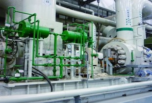
Fig. 4 Appearance of pump station (exterior)

Fig. 5 Appearance of pump station (interior)
3. Introduction of reconstruction work
3.1 Work characteristics
Main characteristics of the work are listed below:
- (1)
- Sequential replacement of old machines and electrical installations with new ones (Figure 6)
We were required to carry out the work while maintaining a certain level of drainage capacity during the reconstruction period. To this end, we removed and installed two main pumps per year (six units replaced in total), and each time carried out a commissioning check to switch from old to new equipment sequentially.
- (2)
- Installation of temporary pier and cofferdam in canal for drainage of pump sump section (Figure 7)
To install trash removal screens in the pump sump section, it was necessary to extend the existing civil engineering structures in the direction of the inflow side and construct a slab and partition walls in the canal. Therefore, we installed a temporary pier in the canal so that heavy machinery could be used on it for crane work and excavation. Moreover, we also conducted temporary water shielding by means of a cofferdam to drain the pump sump.
- (3)
- Reconstruction of foundation for machinery (Figure 8)
The pump facilities to be newly installed during the reconstruction work were expected to have different specifications from those of the old ones. For example, the new main pumps have a vertical shaft, as well as a larger bore due to increased discharge capacity. In addition, the output of the prime mover is also different from before. Consequently, we removed existing machines along with their substructures by cutting the existing concrete, while leaving the existing reinforcing bars of civil engineering structures as they are [Fig. 8 (a)]. After that, openings and substructures tailored to the renewed machines were newly constructed [Fig. 8 (b)].
- (4)
Civil engineering work for seismic retrofitting (Figure 9)
As part of the reconstruction work, we conducted civil engineering work for seismic retrofitting, such as installation of shear reinforcement bars and reinforcement steel sheets in/on the slab, and partition walls of the pump sump.

Fig. 6 Scope of work (by phase)

Fig. 7 Installation of temporary pier and cofferdam,
and construction work in canal

Fig. 8 Reconstruction of machine foundation

Fig. 9 Civil engineering work for seismic retrofitting
(Pump sump section)
3.2 Construction challenges
The challenge level of the work is evaluated as“ difficult”(rated V of VI). During the long work period, we were required to steadily and reliably proceed with the processes one by one while maintaining a certain level of drainage capacity, which was a big challenge to us.
The parties involved always tried to have an overall view of the work, with particular efforts focused on the matters listed below, and implemented elaborate construction PDCA cycles, as part of which periodic project meetings were held in and outside the company. By doing this, we realized the assurance and improvement of work quality and safety while adhering to the prescribed work schedule, and successfully completed the work.
- (1)
- Confirmation of construction conditions by means of careful field investigationVerification of existing civil engineering structures, check for interference of machines and piping, etc.
- (2)
Preparation of efficient renewal schedule
Rational configuration of machine/electric equipment changeover sequence and relocation method
Improvement of workability by devising suitable installation and suspension jigs*
* While an existing pump station building and cranes were to be used continuously, previously used horizontal-type main pumps were to be replaced by vertical-type ones, resulting in an increase in weight and thus making it impossible to lift by crane a full set of assembled pump components at one time. Also, the lifting margin was limited due to the engine exhaust duct layout. Considering these constraints, we produced special jigs (Figure 10).
- (3)
Thorough coordination of work schedule
Progress management always keeping an eye on the overall schedule including other work items (architectural equipment, seismic retrofitting of building, etc.).
- (4)
Assurance and improvement of work safety
Prevention of falls into the fast-flowing canal, etc.

Fig. 10 Carrying-in and emplacement of main pump
using installation and suspension jigs
3.3 Design measures
The range of operational water levels for inside water (Musashi Canal) is short.
→ A control logic was developed to flexibly regulate flow rate by changing rotation speed and discharge valve opening in accordance with inflow volume.
Improved reliability of the cooling system is demanded.
→ To cope with unexpected failure of separately installed radiator fans, a function of automatic switching to backup fans was added.
Space in the pump station building is confined.
→ To maximally ensure the smooth flow of workers and materials, as well as sufficient maintenance space, inventive measures were devised for the layout of exhaust ducts and supports, as well as for the lid of the opening in the vacant space (securing of load capacity to bear the weight of temporarily placed equipment; elimination of unevenness).

Fig. 11 Configuration of vortex suppression devices
4. Application of CFD analysis
4.1 Outline
The pump sump of the Nukata Drainage Pump Station is arranged to receive water that comes from the upstream balancing reservoir and makes a right-angled turn when flowing into the sump. Also, some pumps (No. 3 and 4) were scheduled to be renewed to have larger drainage capacity while partition walls dividing the subsections of the pump sump were to be extended, leading to a greater likelihood of drift flows in the pump sump. Consequently, it was expected that there would be an increased risk of emergence of harmful vortices (i.e. air-entraining vortices and submerged vortices) that could affect the operation of pumps.
As reported in the previous report2), we then analyzed the flow patterns in the pump sump along with the upstream balancing reservoir and carried out a model testing, in order to study the configuration of anti-vortex devices. Fig. 11 shows the configuration of vortex suppression devices optimized using CFD analysis. On top of that, this time we proved the effectiveness of the vortex suppression devices configured with the help of CFD analysis, based on the data obtained through the test operation of real equipment during the comprehensive commissioning conducted prior to the completion of the renewed Nukata Drainage Pump Station. We also checked the validity of the CFD analysis we conducted.
4.2 Field test
- (1)
Measurement of flow velocity in pump sump A pair of three-dimensional electromagnetic velocity meters were used to measure the flow velocity in the pump sump. One velocity meter was installed in each of the left and right water channels divided by a center pier, as shown in Fig. 12.
- (2)
- Observation of water surface flow adjacent to pump suction pipeIn general, the pump sump of a rainwater drainage pump station is designed as a closed conduit, making it difficult to perform direct visual observation of vortices generated while the pump is operating. In this test, we used an industrial endoscope inserted from the pump base to capture and observe the water surface flow adjacent to the pump suction pipe.

Fig. 12 Field test conditions
4.3 Test results
Figure 13 shows the time variations of the flow velocity in the pump sump (stream-wise component in the sump) when the No. 4 pump is independently running. Data revealed that the flow velocity tended to be higher in the left channel than in the right when the pump was viewed from the upstream side. The average flow velocity within the time range indicated in Fig. 13 was 1.89 m/s for the left channel, and 1.47 m/ s for the right channel. Then, these averages were deemed as representative flow velocity values and converted to flow rate, on the assumption that no water-level difference occurs between the left and right channels; as a result, the flow in the left channel accounted for 56% of the total, and that in the right channel 44%.
Figure 14 shows the water surface flow around the pump suction pipe, which was observed by means of an industrial endoscope while the pump was in operation. We found no swirling flow during the test run, and confirmed that no air-entraining vortices would be generated.

Fig. 13 Flow velocity in No.4 pump sump

Fig. 14 Water surface flow adjacent to pump suction pipe
4.4 Reproduction simulation of actual equipment
test by CFD analysis
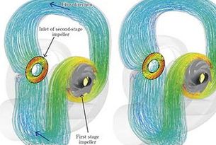
We conducted a steady state analysis using the Reynolds-averaged Navier-Stokes (RANS) model, not taking water surface fluctuations into account. Figures 15 and 16 respectively show a vector diagram of flow velocity in the balancing reservoir and an enlarged view of inflow into the pump sump. The proportion of the flow in both the channels was 58% for the left channel and 42% for the right channel, fairly consistent with the results of the field test.
Figure 17 presents the distribution of the velocity vectors at the water surface, as well as the vortex core lines, in the pump sump. Although several vortex cores are observed, they are not harmful, showing that the vortex suppression devices are effective. Flow patterns at the water surface are also highly consistent with the observation of the actual equipment (Fig. 14); this means that the flow conditions during the actual equipment test were successfully reproduced with good accuracy, by means of the large scale CFD analysis on the balancing reservoir and pump sump.

Fig. 15 CFD analysis results of pump sump along
with balancing reservoir

Fig. 16 Inflow into No.4 pump sump

Fig. 17 CFD analysis results of pump sump
5. Conclusion
The reconstruction work was rated as “difficult” in terms of challenge level, and involved (i) the sequential replacement of equipment in parallel with the retention of a certain level of drainage capability; (ii) provision of vortex suppression measures; (iii) construction of temporary pier and cofferdam in the canal; (iv) civil engineering work for seismic retrofitting; and so on. We were required to adhere to the long work schedule, and had tasks of ensuring and improving work quality and safety. All persons involved are proud that they successfully completed the work by dedicating a long list of creative efforts to tackling design and construction issues on the basis of a good understanding of the characteristics of the worksite.
As the contractor of the work, we received an award under the name of the Chairman of Tone Canal Management and Construction Office Safety Council, for our excellence in safety management in FY2015 (annual award for achieving zero accidents).
Finally, we should mention that we received the guidance and cooperation from many people in and outside our company, including those from the Japan Water Agency, with regard to the reconstruction work. We would like to sincerely express our gratitude to the parties concerned.
References
Recommended articles
Inquiry about Ebara Engineering Review