Issue No. 252〔Delivered Products & Systems〕
Construction of Municipal Waste Treatment Plant
“Clean Plaza Yokote”
Author
Keisuke
TSUKAMOTO*
Kenichi
NISHIYAMA*
Minoru
SASAKI*
Minoru
KANAZAWA*
Koichi
SATO*
Yoichi
HIRAKAWA*
- *
Ebara Environmental Plant Co., Ltd.
1. Introduction
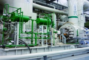
At the end of March 2016, we delivered Clean Plaza Yokote to Yokote City, Akita Prefecture (Figure 1). Clean Plaza Yokote is a new waste treatment plant constructed as an integration of the three aged waste treatment plants in the city. This plant consists of a heat recovery facility capable of processing 95 tons of combustible waste a day using two state-of-the-art, grate-type incinerators and a recycle center capable of treating 9 tons of incombustible and bulk wastes and 21 tons of recyclables per day.
Clean Plaza Yokote is the first waste treatment plant in Akita Prefecture that is built based on the design/ build/operate (DBO) approach (under a 20-year comprehensive contract covering design, building, and operation). For this project Ebara Environmental Plant Co., Ltd., as a representative company, formed a consortium with two local construction companies, Itoken Corporation and Yokote Construction, for design, material procurement, and construction of the plant. Since the plant started operation, a SPC (special purpose company) capitalized by Ebara has undertaken to manage and operate the plant as well as management of recycle waste over the next 20 years.

Fig. 1 Clean Plaza Yokote
2. Overview of the plant
Figure 2 shows the entire plant.

Fig. 2 Overview of the facility
2.1 Waste receiving system
2.2 Heat recovery facility

Fig. 3 Process flow at the heat recovery facility
| Receiving and feeding equipment | |
| Waste bunker | Two-stage bunker consisting of input bunker and storage bunker |
| Waste crane | Two full automatic cranes |
| Incineration equipment | |
| Incinerator | Full continuous-combustion, grate-type incinerator (Model HPCC21 from Ebara) |
| Capacity: 95 t/d (47.5 t/d x 2 units) | |
| Combustion-gas cooling equipment | |
| Boiler | Natural-circulation water tube boiler with superheaters |
| Evaporation: max. 6.4 t/h x 2 units | |
| Steam conditions: 4.0 MPa x 400 ℃ (at the outlet of the superheater) | |
| Generating equipment | |
| Steam turbine | One-extraction 9-stage impact type condensing turbine |
| Generator | Three-phase synchronous generator with a capacity of 1 670 kW |
| Flue gas treatment equipment | |
| Method of cooling flue gas | Water injection |
| Dust collection method | Bag filter |
| NOx reduction method | Selective non-catalytic reduction based on urea solution |
| HCl and Sox removal method | Dry (slaked-lime blowing) |
| Measures against dioxins and mercury | Activated carbon blowing |
| Waste-heat utilization equipment | |
| Major usage of waste heat | Road heating by using turbine exhaust |
| Ash-removal and -treatment equipment | |
| Incinerated ash | Carried out using ash bunker and crane to be recycled as raw material for cement at the Ofunato factory of Taiheiyo Cement Corporation |
| Fly ash | Chelated and then carried out using ash bunker and crane |
| Wastewater treatment equipment | |
| Plant waste water | Coagulated and sand-filtered, and then reused within the premises, without being discharged |
| Domestic waste water | Treated in a combined septic tank, and then discharged |
| Refuse sewage | Circulated inside the bunker |
| Restricted substance | Criteria value | |
| Dust | g/m3(NTP)※1 | 0.007 or less |
| Hydrogen chloride | ppm※1 | 50 or less |
| Sulfur oxides | ppm※2 | 30 or less |
| Nitrogen oxides | ppm※1 | 80 or less |
| Carbon monoxide | ppm※1(average per 4 hours) (average per hour) | 20 or less 80 or less |
| Dioxins | ng-TEQ/m3(NTP)※1 | 0.04 or less |
※2 Unconverted value under dry condition
2.3 Recycle center

Fig. 4 Process flow at the recycle center
| Line for incombustible waste and bulk waste | |
| Capacity | 1.8 t/h |
| Crushing method | Low-speed, biaxial shearing + high-speed vertical rotation |
| Screening and recovery method | |
| 1)Iron | Separated with a magnetic separator for use as recyclables |
| 2)Aluminum | Separated with an aluminum separator for use as recyclables |
| 3)Residua combustible and incombustible waste | Incinerated at the heat recovery facility |
| Line for cans | |
| Capacity | 0.38 t/h |
| Screening and recovery method | |
| 1)Iron | Separated with a magnetic separator and compacted with a compacting machine for reuse as pressed steel cans |
| 2)Aluminum | Separated with an aluminum separator and compacted with a compacting machine for reuse as pressed aluminum cans |
| 3) Inappropriate waste | Manually separated and crushed |
| Line for bottles | |
| Capacity | 1.14 t/h |
| Screening and recovery method | |
| 1)Returnable bottles | Manually separated and collected in special containers as recyclables |
| 2)Clear bottles | Manually separated and recycled as cullet |
| 3)Brown bottles | Manually separated and recycled as cullet |
| 4)Other color bottles | Manually separated and recycled as cullet |
| 5)Inappropriate waste | Manually separated and then crushed |
| Line for waste paper | |
| Capacity | 2.58 t/h |
| Recovery method | |
| 1)Newspaper | Compression baled for use as recyclables |
| 2)Magazines | Compression baled for use as recyclables |
| 3)Corrugated cardboard | Compression baled for use as recyclables |
| Other recyclables | |
| 1)Metals | Stored and recovered for use as recyclables |
| 2)Dry batteries | Stored and recovered |
| 3)Small home appliances | Stored and recovered for use as recyclables |
| 4)Glass and ceramic products | Stored and recovered for use as recyclables |
| 5)Clothes | Stored and recovered for use as recyclables |
| 6)Fluorescent tube | Stored and recovered |
3. Construction schedule
Table 4 shows construction milestones.
| Contract conclusion | Jun-2013 |
| Start of land creation | Aug-2013 |
| Start of building construction | Mar-2014 |
| Start of plant installation | Jul-2014 |
| Initial power receiving | Aug-2015 |
| Start of comissioning | Nov-2015 |
| Performance test | Feb-2016 |
| Completion | End of March 2016 |
4. Features of the plant
4.1 Adoption of the grate-type incinerator HPCC21
4.2 High efficiency power generation using steam condition of 4 MPa x 400 °C
With top priority placed on safe, stable waste treatment, the plant was designed to improve power generation efficiency with the goal of acting as a regional energy center. For improving power generation efficiency, the most critical thing is to increase the steam temperature and pressure of the boilers. Based on our past accomplishments, we designed the steam conditions with 4 MPa x 400 °C, the highest level for boilers with the same scale as in this plant in Japan, as well as increasing the vacuum degree of the condensers. As a result, we obtained the gross power generation efficiency of 19.6% as a design value. In Figure 5 we added the value for Clean Plaza Yokote (shown as a star mark) in the Reference Fig. 1-2: Actual and Calculated Power Generation Efficiencies at Waste Incineration Plants from Reference Material #1 in Manual for Maintaining Facilities for Efficient Power Generation by Refuse Incineration 2) issued by the Ministry of the Environment. Compared with the past actual values and the calculated values for 4 MPa x 400 °C, the generating efficiency of ca. 20% achieved at Clean Plaza Yokote is proven very high for plants with a capacity of 100 t/d.

Fig. 5 Power generation efficiency at Clean Plaza Yokote
4.3 Function as a logistics support center during disasters
(1)Earthquake-resistant design
(2)Waste treatment during disasters
The plant has a waste bunker with a capacity of 3600 m3 to store as much disaster waste as possible, corresponding to a capacity for 15 days.
In addition, the plant is designed to allow an incinerator and a boiler to be started with an emergency diesel generator so that waste can be treated even if power from the electrical grid is lost during a disaster. Once activated, the incinerator and the boiler can start up the regular steam-turbine generator, allowing the second incinerator to be operated.
Furthermore, the plant is equipped with a well-water pumping system and a pretreatment system that allow continuous operation of the incinerators by supplying well-water as plant water even if the waterworks is lost.
(3)Logistics support center
4.4 Active introduction of natural energies
(1)Snow storage chamber (Figure 6)

Fig. 6 Snow storage chamber
(2)Solar power generation system (Figure 7)

Fig. 7 Solar power generation system
5. Plant operating condition
5.1 Heat recovery facility
The heat recovery facility officially started to receive waste at the end of October 2015 and started the hot commissioning in November. The pre-use self inspection defined by METI for thermal power plant was completed before the end of December, followed by the preliminary performance test in mid-January 2016 and the acceptance performance test in mid-February.
Table 5 shows the results of the load tests conducted as part of the pre-use self inspection. The boilers were tested-approximately with a maximum continuous rating of 6.4 t/h and the steam-turbine generator was tested with the rated output of 1 670 kW. Table 5 shows the main-steam flow rates, temperatures, pressures, generator outputs, and other conditions observed in the tests. Approximately 2 t/h of the main steam were surplus, which were made to bypass the turbine. The gross power generation efficiency is, by calculation, 16.6%. If the main steam surplus is factored in, the efficiency becomes 20%, which satisfies the design value of 19.6%. Table 6 shows the measurement results on the flue gas during the acceptance performance testing.
With an oxygen concentration at boiler-outlet of 2.7%, the plant demonstrated stable operation with a very low air ratio of approximately 1.2. The average concentrations of CO and NOx were 10 ppm (for #1) and 5 ppm (for #2), and 58 ppm (for #1) and 47 ppm (for #2), respectively, proving to be sufficiently lower than the criteria values. The measured values for dioxins and other restricted substances also sufficiently satisfied the emission criteria.
| Measured item | Unit | Result | |
| Boiler main-steam flow rate (#1 and #2) | Z1/Z2 | t/h | 6.15/6.13 |
| Boiler main-steam temperature (#1 and #2) | ― | ℃ | 400/401 |
| Boiler main-steam pressure (# 1 and #2) | ― | MPa | 3.94/3.95 |
| Main-steam flow rate at turbine inlet | ― | t/h | 9.82 |
| Turbine-bypassing steam amount | Zb | t/h | 2.10 |
| Generator output | Pg | kW | 1670 |
| Amount of waste treated (#1) | B1 | t/h | 2.01 |
| Amount of waste treated (#2) | B2 | t/h | 2.04 |
| Waste calorific value (calculated value) | H | kJ/kg | 8940 |
| Gross power generation efficiency※1 Gross power generation efficiency※2 with turbine-bypassing amount factored in | η η’ | % | 16.6% |
| 20.0% | |||

| Measured item | Unit | Judgement criteria | Result | Judge | |
| #1 | #2 | ||||
| Incineration capacity | % | ≧100% (≧47.5 t/d each) | ≧100% | ≧100% | Pass |
| Ignition loss | % | ≦5 | <0.1% | ≦0.9% | Pass |
| Dust concentration | g/m3(NTP) | ≦0.007 | <0.002 | <0.002 | Pass |
| Sulfur oxides | ppm | ≦30 | 22 | 17 | Pass |
| Nitrogen oxides | ppm | ≦80 | 58 | 47 | Pass |
| Hydrogen chloride | ppm | ≦50 | 29 | 24 | Pass |
| Carbon monoxide | ppm(average per 4 hours) | ≦20 | 10 | 5 | Pass |
| Dioxins | ng-TEQ/m3(NTP) | ≦0.04 | 0.00054 | 0.0039 | Pass |
| 0.00016 | 0.0081 | Pass | |||
| Ammonia | mg/m3(NTP) | ― | 1.1 | 1.7 | ― |
| Mercury | mg/m3(NTP) | ― | <0.01 | <0.01 | ― |
| Boiler outlet oxygen | %(wet) | ― | 2.5 | 2.9 | ― |
| Air ratio | ― | ― (with 25% water content in exhaust gas) | 1.2 | 1.2 | ― |
5.2 Recycle Center
| Crushed iron | 98.3% | Clear bottles | 100.0% |
| Crushed Aluminum | 98.1% | Brown bottles | 100.0% |
| Steel cans | 99.6% | Other bottles | 100.0% |
| Aluminum cans | 100.0% |
6. Remote Monitoring

Fig. 8 Remote support center
7. Conclusion
Finally, we would like to express our deep gratitude to the people in Yokote City and all those concerned who provided great guidance and assistance for the construction of the plant.
References
Recommended articles
Inquiry about Ebara Engineering Review